A QUANTUM LEAP IN ENERGY GENERATION
Welcome to the nexus of historical ingenuity and future-defining technology. For centuries, the principle of converting mechanical work into electrical energy has been the engine of global progress. Yet, true innovation demands a reappraisal of even the most fundamental concepts. We invite you to explore a development that not only respects the past but fundamentally reshapes the future of power generation.
A new electric generator is a radical departure from conventional electromagnetic designs. Its operating principle draws its lineage from earlier foundational works which demonstrated the power of electrostatic induction to create repeatable charge separation. These historical devices hold the key to unlocking extraordinary efficiency.
Explore our journey from historical curiosity to market-ready, high-efficiency generator. Discover how the advancements in materials science and electrostatics management are set to redefine the energy landscape, offering a sustainable and exceptionally efficient solution for the world’s increasing power demands. The future of energy is here—it’s time to generate it smarter.
From 1762 to Today: The Electrophorus Reimagined
Our journey to a new era of energy generation began centuries ago, with a seemingly simple invention.
The Historical Foundation: The Electrophorus
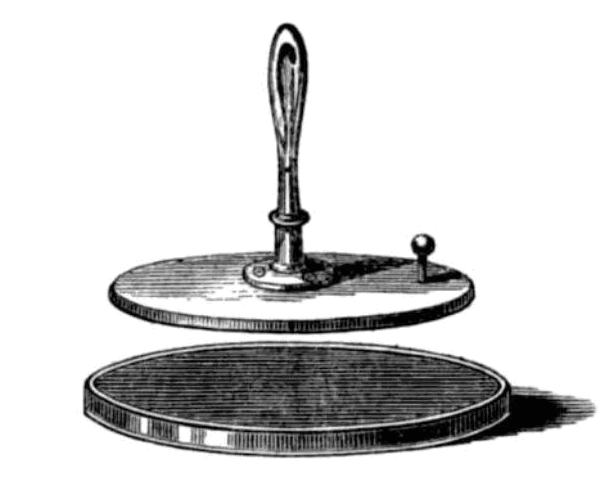
The story of the new type of generator starts in 1762, when the Swedish professor Johan Carl Wilcke invented the first version of the Electrophorus, a device that consists of a flat dielectric plate (the “cake”), an insulating handle and a metal disk.
The Electrophorus works on the principle of electrostatic induction:
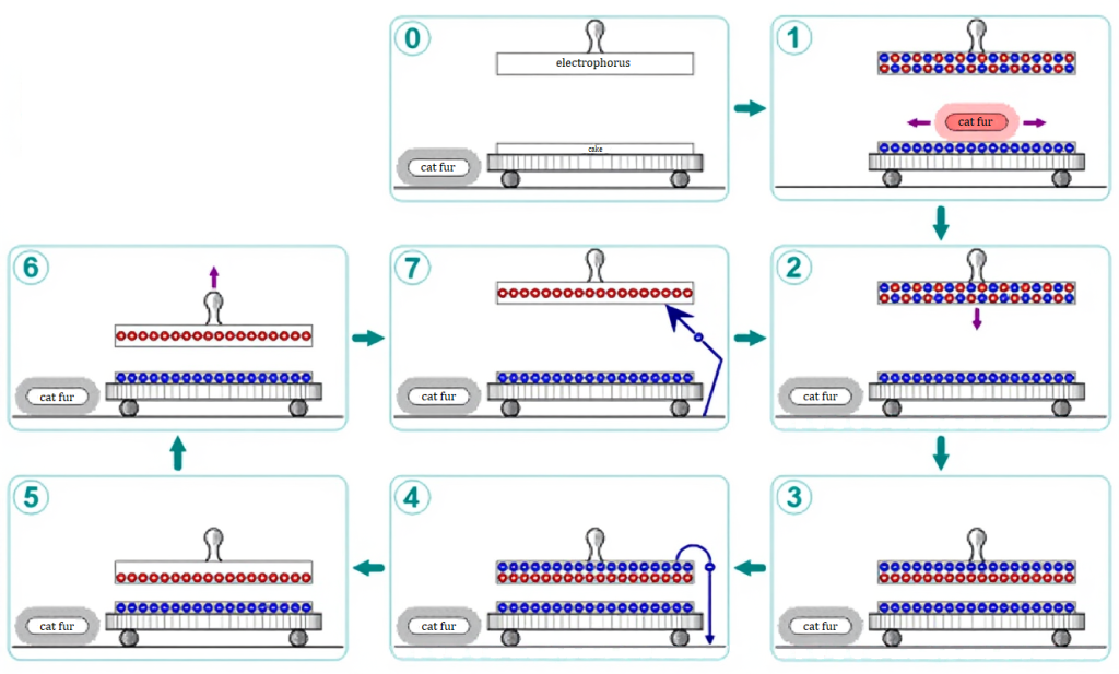
- Charging the Cake: Rubbing a piece of fur over the dielectric “cake” gives its surface a negative charge. Since the “cake” is an insulator, this charge is stable and does not deplete easily.(1)
- Induction: A conductive metal disk is placed upon the charged “cake”. The negative charge on the cake induces a charge separation in the disk. (2, 3)
- Grounding: The disk is momentarily grounded (while still on the cake). This allows electrons from the disk’s top to be repelled to the ground, leaving the disk with a net positive charge. (4, 5)
- Retention: When the disk is lifted away, it retains this net positive charge. (6, 7)
- Repetition: Therefore, the process can be repeated indefinitely.
The key benefit of the Electrophorus is its ability to produce an “unlimited amount of induced charge” because the cake’s charge is not depleted by the process. This led Alessandro Volta to call it the “elettroforo perpetuo” (the perpetual electricity bearer). This invention marked the beginning of the development of so-called influence machines, working by repeated electric induction.
The development of influence machines lasted until the early 1900s. Some major developments of this type:
- 1788 Nicholson’s doubler
- 1864 Holtz machine
- 1883 Wimshurst machine
The Initial Challenge: Converting Static Energy
The energy stored in a stable electrostatic field can be converted into usable electrical energy. In the electrophorus setup, there is an electrostatic attraction between the charged dielectric plate and the metal plate. Moving the charged metal plate away from the dielectric requires mechanical work against the electric field. This means the mechanical work put in is roughly equal to the electrical energy obtained.
$$W_{mech} \approx W_{elect}$$
Like every traditional generator, the electrophorus acts as a transducer, converting mechanical work into electrical energy. The goal of our journey was to find methods that eliminate the mechanical work against the electric field so that no work would need to be done to separate the plates. This led to addressing two major issues.
Key Issue #1: Eliminating Work in the Electrostatic Field
We asked: Is it possible to move the metal plate without mechanical work against the electric field? The answer lies in the physics of work in an electrostatic field:
$$W = qEd \cos(\theta)$$
(Where \({W}\) is work, \({q}\) is magnitude of charge, \({E}\) is electric field strength, \({d}\) is displacement of charge, \({\theta}\) is angle between displacement and electric field vectors).

For the work (W) to be zero, the term cos(θ) must be zero. This occurs when the angle (θ) between the displacement and the electric field vectors is 90 degrees (perpendicular).
If two surfaces are parallel, the electric field between them is perpendicular to their surfaces. A force acting in one direction (e.g., horizontal) has zero effect on the motion or force in a perpendicular direction (e.g., vertical).
Based on this principle, the rotational motion of two parallel surfaces (disks) can be achieved without substantial mechanical work against the electric field.
Source: Georgia State University
This concept led to a new type of electrostatic generator, notably explored by German physicist Heinrich Wommelsdorf in the early 1900s. His design involved segmented disks rotating parallel to each other. He effectively transformed the influence machine into a capacitance machine, which he termed a “Kondensatormaschine” (Condenser Machine). Wommelsdorf’s design also addressed the fundamental physical requirement for high capacitance: that the distance (gap) between the electrodes (segments) had to be small, ideally an order of magnitude smaller than the segments’ size (width).
Recognizing the lower mechanical losses of capacitance electrostatic generators, their development also accelerated.
In 1937, Robert J. Van de Graaff filed an improved capacitance electrostatic generator patent (filed in 1937; granted as US 2,194,839 in 1940), which described a machine capable of delivering significant power. (This invention is not the well-known belt-type Van de Graaff generator.)
Later, in 1960, A. S. Denholm further developed and effectively doubled the performance of the generator described in the Van de Graaff patent (US 3,107,326).
Key Issue #2: Eliminating the Braking Torque
A capacitance electrostatic generator solution, however, introduced a new problem: the rotating disks generated a braking torque. This is a general issue for capacitance electrostatic generators; the phenomenon and its physics are described in detail in Denholm’s patent. Electrostatic generators typically produce relatively small torques compared to machines that rely on magnetic fields; the low torque often necessitates increasing the generator’s size to provide adequate power.
The simplified universal formula for this braking torque with constant voltage is:
$$M(\theta) = \frac{1}{2} V^2 \frac{dC(\theta)}{d\theta}$$
(Where \({M}(\theta)\) is torque, \({V}\) is voltage, \(\frac{dC(\theta)}{d\theta}\) is the rate of change of capacitance with respect to angle).
This shows that the torque \(({M}(\theta))\) depends exclusively on the change in total capacitance \(({dC})\) during the rotor’s rotation. A braking force is generated wherever the capacitance changes.
Our exploration continued to find a way to eliminate it. If the net change in capacitance is zero \(({dC} = 0)\) the braking torque is also zero \(({M}(\theta) = 0)\). This would allow rotational motion without substantial mechanical work against the field.
The Solution: The Hyde Generator
The ideal solution is a capacitance electrostatic generator where:
- The rotor moves perpendicular to the electric field.
- The rotor’s design causes no net change in the system’s capacitance.
With these technical solutions, the electrostatic braking effects on the rotor(s) are almost completely eliminated.
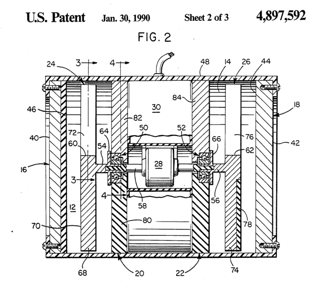
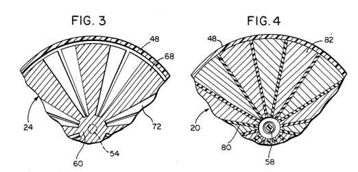
Both key issues were solved by the design described in the 1990 patent US 4,897,592 by William W. Hyde.
Hyde’s design places a symmetrical, segmented rotor between charged and grounded stator plates. This rotor acts as an electrostatic “shield”. Because of its symmetry, the total system capacitance remains constant as it rotates. This represents an elegant balance of forces, nearly eliminating the electrostatic braking effects.
As a result, the system can convert electrostatic energy to electric energy with a reduced input of mechanical energy.
The mechanical input to the system may therefore be substantially limited to mechanical bearing losses and windage during conversion of electrostatic field energy to electrical energy.
Quotes from Hyde’s patent:
„rotors in a plane perpendicular to the field flux”
”…since there is no net change in capacitance thereby enabling the system to convert energy with a reduced input of mechanical energy”
„…rotation of the rotors … does not perform any substantial work against the external electric fields”
And the result, in Hyde’s words: “…the present invention requires less than ten percent of the electrical output energy for the mechanical input.”
Is it incredible? Let’s have some fun. Ask the AI! Is there any resistance or breaking torque in Hyde’s system? Give the prompt below to any AI model and check the result.
A theoretical electrostatic generator is constructed from the following components:
- An Electrode: A disk-shaped electrode made of a conductive material. This disk consists of a single, non-segmented surface.
- A Stator: A disk-shaped stator, identical in size to the electrode, made of a conductive material. It is divided into an even number of segments by radial lines extending from the center. These segments cover the entire surface of the disk. Each segment is electrically isolated from the others and is electrically connected to ground.
- A Rotor: A disk-shaped rotor, identical in size to the stator, made of a conductive material. It consists of radial segments.
   * The angular size of these rotor segments is identical to the size of the stator segments.
   * The total number of rotor segments is half the number of stator segments.
   * They are arranged equally spaced, with a gap equivalent to one segment's width between each segment. (This means the rotor segments cover exactly 50% of the total area).
   * All rotor segments are electrically connected to each other and to ground.
- A Shaft:  A bearing-mounted shaft, onto which the rotor is centrally fixed.

Assembly and Configuration:
1.  The Electrode and the Stator are placed opposite and parallel to each other.
2.  The Rotor is inserted between the Electrode and the Stator, perfectly centered and parallel to both.
3.  The distance (gap) between the Electrode, Rotor, and Stator is small, an order of magnitude smaller than the size (width) of the segments.
4.  The entire device is housed and operated in a vacuum.

Operation and Question:
A voltage is applied to the Electrode, and then the Rotor begins to rotate.

Does the resulting electric field exert any resistance or breaking torque against the rotational motion of the rotor? Give a short answer.
The Next Hurdle: Power-to-Size Ratio
If Hyde’s design is so effective and can produce a net energy gain, why isn’t it widely used?
The issue lies in its poor power-to-size ratio.
The Hyde generator, as described in the patent, required rotors with a diameter of several meters to deliver a relatively low net power output. A solar panel system, for example, offers a much better power-to-size ratio. Let’s see, why!
The power output (P) of an electrostatic generator is given by the simplified general formula:
$$P = \frac{\epsilon_0 \epsilon_r A U^2 n f}{2d} = \frac{1}{2} C U^2 n f$$
(Where \({A}\) is area, \({U}\) is voltage, \({f}\) is frequency, \({n}\) is the number of segments, \({d}\) is the distance between plates, \({\epsilon_0}\) is vacuum permittivity, and \({\epsilon_r}\) is the relative dielectric constant).
The problem with the original Hyde design is the inherent small value of vacuum permittivity \(({\epsilon_0} = 8.8541 \times 10^{-12})\) and the great value of distance between plates \(({d})\) due to the rotor’s thickness. To increase power, prior solutions often focused on increasing the number of segments \(({n})\) and surface area \(({A})\). Because of the rotor’s thickness, the separation between the electrodes is already large, which necessitates increasing the dimensions (width) of the segments; this, in turn, leads to an overall increase in machine size. For example, available data on the prototype Hyde generator mentions 480 segments on the stators.
However, this leads directly to a enormous physical size. As mentioned earlier, the rotors must have a diameter of several meters. Moreover, rotating these large-diameter disks poses an extremely significant technical challenge.
On the Calculations page, you can find special calculators to check the physical size of the disks. Try it, but remember that relative dielectric constant in Hyde’s solution is typically limited to 1.2-1.5.
The Breakthrough: New Material Technology
To achieve a compact size while maintaining a useful power output, we shifted focus to the factor of \({\epsilon_r}\), the relative dielectric constant of the material between the plates.
We have found a study about insulating materials that can achieve a dielectric constant of the order of a thousand without mechanical drag or friction.
Crucially, these new materials:
- Significantly boosts power output by directly increasing the \({\epsilon_r}\)value in the equation.
- Does not substantially increase the mechanical energy required to rotate the rotors.
- Has a high dielectric strength, allowing us to safely increase the operating voltage (V) as well.
This new material technology is the key that finally unlocks the potential of the Hyde generator design, moving it from a large, theoretical device to a compact, highly efficient, and practical energy solution.
The Hybrid Dielectric System: A new study
A previously undocumented phenomenon: the specific interaction between a solid and a liquid dielectric in a parallel layer arrangement.
The study is about a new variable-capacitance capacitor design that uses a parallel arrangement of a high-dielectric-constant solid layer and a specific polar liquid dielectric.
The “Conducting” Liquid Phenomenon
When two layers of insulating material with different dielectric constants (k1 and k2) are placed parallel to the capacitor’s plates, the resulting capacitance can typically be calculated using the formula for series-connected capacitors. The two different layers represent two different capacitors (C1 and C2) in a series connection.
$$\frac{1}{C_{\text{total}}} = \frac{1}{C_1} + \frac{1}{C_2}$$
In a series connection of two dielectric layers, the resulting capacitance is always lower than that of the weaker (lower \({\epsilon_r}\)) layer.
However, the study reveals that with certain solid-liquid pairs, the liquid dielectric acts as a unique “intermediate” layer. Under the influence of the electric field, the liquid exhibits “conducting properties” with respect to the electric flux, not by transporting charge (it remains an electrical insulator), but through a special, highly efficient molecular polarization and orientation.
This unique behavior essentially nullifies the capacitive effect of the liquid layer in the series circuit. Consequently, the total resulting capacitance approximates the capacitance of the solid layer alone.
Experimental Confirmation
Our experimental measurements were performed using a small and simple device. It consists of two 19 mm diameter ceramic disks (a barium titanate-based ceramic) (\(\epsilon_{r} \approx 8000\)) and one aluminium disk. One side of the ceramic disks is coated with a silver conductive material. There is a 1 mm gap between the aluminum disk and the ceramic disks. The gap was filled with various light polar liquids, including methanol, ethanol, 1-Propanol (alcohols). We revealed a striking result: the measured capacity (up to \(61.0 \text{ nF}\)) was nearly a thousand times greater than the value predicted by the traditional series capacitance formula (\(73.6 \text{ pF}\)). The measured capacity approached the high value of the solid ceramic. This dramatic capacity increase is achieved while the liquid layer maintains a frictionless relative movement between the generator plates.
The Formula for Success
The high-capacity benefit means that the system’s performance is no longer hampered by small \(\epsilon_{r}\) values. The new system combines the low mechanical loss (frictionless motion) of the liquid layer with the high electrical output afforded by the massive effective capacitance, moving the Hyde generator from a theoretical curiosity to a viable path for next-generation power generation.
The Final Step
The pairings of insulating materials described in the study and successfully tested by us do enable a significant capacity increase in the system. This is indeed a huge success. However, this special combination of insulating materials also comes with side effects that complicate the technical implementation.
Technical Challenges of the Hybrid System
- Inter-Electrode Capacitance: Furthermore, it was observed that when a larger number of ceramic electrodes are used, adjacent ceramic electrodes also form capacitance with each other through the liquid. This phenomenon reduces the maximum achievable capacitance difference \(\Delta C\).
- Thermal Management: During high-frequency operation, the ceramic material generates a noticeable amount of heat due to polarization losses.
Outlook
In our opinion, these phenomena are manageable, and a significant capacitance difference can be maintained between the electrodes. We are working on it.
The only question is, who will be the first to actually realize this? Are we in a race to build the compact Hyde generator? And who will win?
Not Elon Musk, we hope!